RSTP vs STP — Key Differences Explained
RSTP vs STP — complete comparison of Rapid Spanning Tree Protocol vs Spanning Tree Protocol. Convergence time, port…
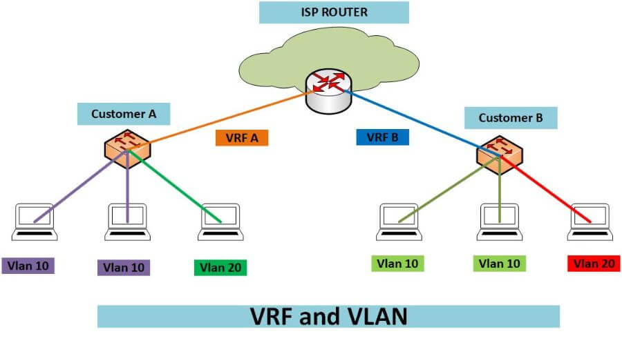
Both create separation, but at different layers, and confusing them leads to designs that appear segmented and are not.
The critical implication: VLANs alone do not prevent routing between them. If a router or Layer 3 switch has an interface in VLAN 10 and VLAN 20, traffic will flow between them unless you write an ACL. People frequently believe VLANs provide isolation when what they have is separate broadcast domains joined by a router that happily forwards between them.
| VLAN | VRF | |
|---|---|---|
| OSI layer | 2 | 3 |
| Separates | Broadcast domains | Routing tables |
| Runs on | Switches | Routers and Layer 3 switches |
| Identifier | VLAN ID, 1–4094 (12-bit 802.1Q field) | VRF name, plus a route distinguisher |
| Carried between devices by | 802.1Q trunk tagging | Separate links, sub-interfaces, or MPLS labels |
| Overlapping IP addresses | No, one routing table sees them all | Yes, each VRF is independent |
| Traffic between instances | Routed by default, if an L3 interface exists in both | Blocked by default, requires route leaking |
| Scale limit | 4,094 per L2 domain | Thousands, platform dependent |
| Typical use | Segmenting one site’s users, voice, guests, IoT | Multi-tenancy, keeping business units or customers separate |
A VLAN tags frames with a 12-bit ID so one physical switch behaves as several independent switches. Ports in VLAN 10 never receive VLAN 20’s broadcasts. Trunk links carry multiple VLANs between switches by tagging each frame.
Switch(config)# vlan 10
Switch(config-vlan)# name USERS
Switch(config)# vlan 20
Switch(config-vlan)# name GUEST
Switch(config)# interface GigabitEthernet0/5
Switch(config-if)# switchport mode access
Switch(config-if)# switchport access vlan 10
Switch(config)# interface GigabitEthernet0/24
Switch(config-if)# switchport mode trunk
Switch(config-if)# switchport trunk allowed vlan 10,20A VRF gives the router a completely separate routing and forwarding table. Interfaces are assigned to a VRF, and traffic in one VRF is invisible to another, including its routes, its ARP table and its addresses.
Router(config)# vrf definition TENANT-A
Router(config-vrf)# rd 65000:10
Router(config-vrf)# address-family ipv4
Router(config-vrf-af)# exit
Router(config)# interface GigabitEthernet0/1
Router(config-if)# vrf forwarding TENANT-A
Router(config-if)# ip address 192.168.1.1 255.255.255.0Note that assigning a VRF to an interface removes any IP address already on it, configure the VRF first, then the address, or you will wonder where the address went.
Router# show ip route vrf TENANT-A
Router# show ip arp vrf TENANT-A
Router# ping vrf TENANT-A 192.168.1.10Every verification command needs the vrf keyword. Forgetting it is the most common source of “the route is missing” confusion, you are looking at the global table.
In a real design they are layered. VLANs segment at the access layer; VRFs enforce that the segmentation survives at Layer 3.
Router(config)# vrf definition GUEST
Router(config-vrf)# rd 65000:20
Router(config-vrf)# address-family ipv4
Router(config)# interface Vlan20
Router(config-if)# vrf forwarding GUEST
Router(config-if)# ip address 192.168.20.1 255.255.255.0Now VLAN 20’s gateway lives inside the GUEST VRF. Guest traffic has no route to the corporate VRF at all, not because an ACL denies it, but because the route does not exist. That is a stronger guarantee than a filter, because there is no rule to misconfigure or accidentally reorder.
Sometimes a shared service, DNS, a management server, internet egress, must be reachable from several VRFs. This requires deliberate route leaking with route targets:
Router(config)# vrf definition TENANT-A
Router(config-vrf)# address-family ipv4
Router(config-vrf-af)# route-target export 65000:10
Router(config-vrf-af)# route-target import 65000:100 ! shared services
Router(config)# vrf definition SHARED
Router(config-vrf)# address-family ipv4
Router(config-vrf-af)# route-target export 65000:100
Router(config-vrf-af)# route-target import 65000:10The asymmetry is the point, a tenant imports shared services, but shared services does not import every tenant’s routes to every other tenant. Our Cisco multi-VRF lab walks through a working configuration. This is how hub-and-spoke and extranet topologies are built in MPLS L3VPN, and our Cisco multi-VRF lab walks through a working configuration.
| Requirement | Use |
|---|---|
| Separate users, voice and guests on one switch | VLANs |
| Reduce broadcast traffic | VLANs |
| Guest network that genuinely cannot reach corporate | VLAN + VRF, or VLAN plus strict ACLs |
| Two acquired companies both using 10.0.0.0/8 | VRF, only VRFs handle overlapping space |
| Managed service provider, per-customer isolation | VRF, usually with MPLS |
| Regulatory separation, cardholder data, OT, medical | VRF, because it is provably separate rather than filtered |
| Separate internet egress paths for different departments | VRF |
| Home or small office | VLANs alone are sufficient |
“I put them in different VLANs so they are isolated.” Not if a Layer 3 device has an interface in both. Inter-VLAN routing is on by default on a Layer 3 switch. You need ACLs or VRFs.
Losing an interface address. Applying vrf forwarding strips the existing IP. Always set the VRF first.
Management access disappearing. Put an interface in a VRF and SSH, SNMP, NTP and syslog to it stop working unless you specify the VRF in each command or use a dedicated management VRF.
Routing protocols need VRF awareness. OSPF needs a separate process per VRF; EIGRP and BGP use address-family blocks. A protocol configured globally will not populate a VRF’s table.
Router(config)# router ospf 10 vrf TENANT-A
Router(config)# router bgp 65000
Router(config-router)# address-family ipv4 vrf TENANT-AHardware limits. VRFs consume TCAM. A switch that supports “VRF-Lite” may support only a handful, and exceeding it fails in ways that are not always obvious. Check the platform data sheet before designing around a large number.
Yes, and that is the normal design. VLANs segment Layer 2; the VLAN’s gateway interface is placed in a VRF so the segmentation extends to Layer 3.
At Layer 2, yes. But if any router or Layer 3 switch has interfaces in both VLANs, it will route between them by default. VLANs separate broadcast domains, not necessarily reachability.
Yes, that is one of the main reasons to use them. Each VRF has its own routing table, so 192.168.1.0/24 can exist independently in several VRFs on the same router.
VRFs without MPLS. You get separate routing tables on the device, and carry them between devices using separate physical links or 802.1Q sub-interfaces rather than MPLS labels. It is how most enterprises deploy VRFs.
VLANs are capped at 4,094 by the 12-bit 802.1Q field. VRFs are limited by platform memory and TCAM, anywhere from a handful on an access switch to thousands on a service provider router.
Structurally, yes. An ACL denies traffic that could otherwise be routed, so a misordered or removed rule opens the path. A VRF means no route exists between the domains at all, there is nothing to misconfigure. Route leaking is explicit and visible.
One response to “VLAN vs VRF — What Each Separates and When to Use Both”
Very well explained! Thank you, Jaspreet! ????