
Network Topology — Types, Diagrams and When to Use Each
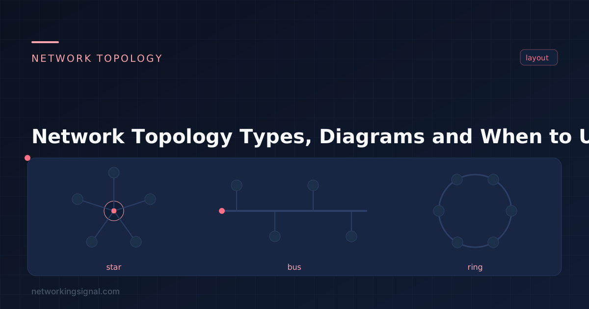
The five network topologies explained — bus, star, ring, mesh and hybrid — with a side-by-side comparison of…
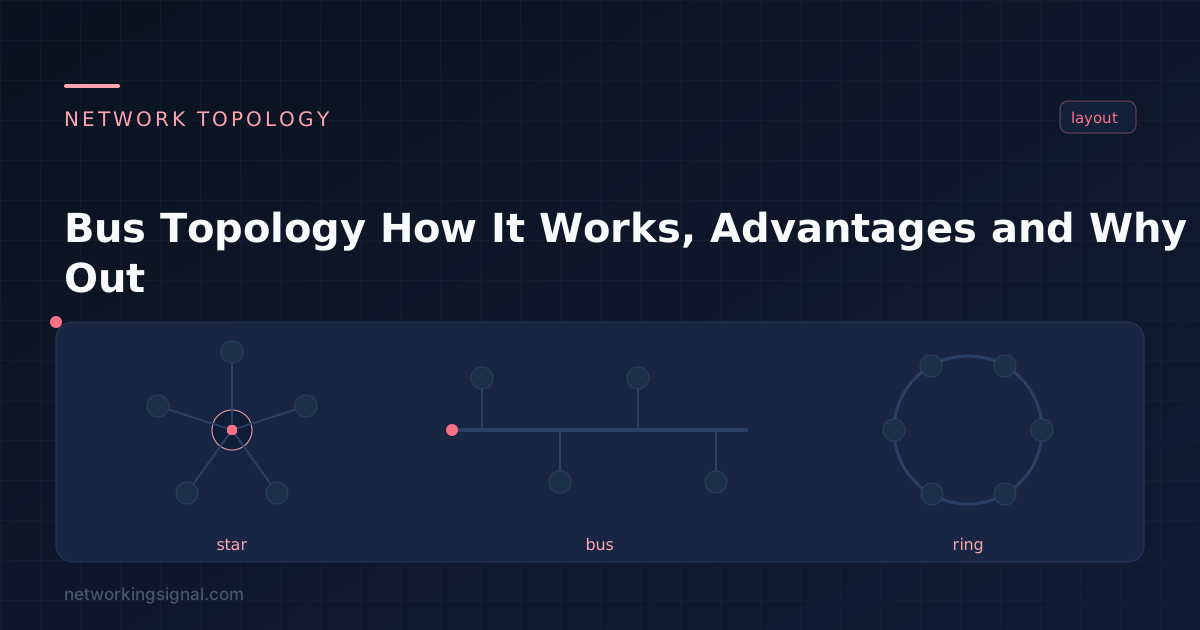
Bus topology connects every device on the network to a single shared cable, the bus, with a terminating resistor at each end. There is no central device. Every signal placed on the cable travels the full length of it and reaches every station.
It was the layout of the original Ethernet standards, and understanding it explains a lot of networking vocabulary that still exists today, collision domain, CSMA/CD, half duplex. In production networks it is effectively extinct, replaced by star topology.
| Part | Purpose |
|---|---|
| Backbone cable | The single coaxial run that carries all traffic. In 10BASE2 this was RG-58 thin coax; in 10BASE5 it was thick yellow coax. |
| Tap / T-connector | How a station joins the cable. 10BASE2 used a BNC T-connector inline; 10BASE5 used a “vampire tap” that pierced the cable jacket. Not an RJ-45, that connector belongs to twisted pair. |
| Drop cable | On 10BASE5 only, the short AUI cable from the tap to the station’s transceiver. |
| Terminator | A 50-ohm resistor at each end of the bus. Without it, signals reflect back down the cable and corrupt every transmission. This is the part that made bus networks fragile. |
The terminator is the detail most explanations skip, and it is the single most important component. Remove one terminator, or break the cable anywhere, which creates two unterminated ends, and the entire segment stops working, not just the devices past the break.
Because the cable is shared, two stations can start transmitting at almost the same instant, neither hears the other yet because the signal has not reached it. The signals overlap and both frames are destroyed. That is a collision.
Ethernet handled this with CSMA/CD (Carrier Sense Multiple Access with Collision Detection): a station that detects a collision sends a jam signal, then both parties wait a random backoff interval before retrying, doubling the possible wait after each successive collision.
The consequence is the defining weakness of bus topology: every station shares one collision domain. Ten megabits is not ten megabits per device, it is ten megabits split across everyone, and it degrades faster than linearly as stations are added, because more stations means more collisions means more retransmissions. This is exactly what switches fixed by giving each port its own collision domain.
A single bus has no redundancy by design. The standard workaround was a dual-bus layout, two independent cables, each station tapped into both, so a break on one bus leaves the other carrying traffic. FDDI’s dual counter-rotating ring used the same idea in ring form. In practice, dual bus doubled the cabling cost of a topology whose only real advantage was cheap cabling, which is part of why it never caught on.
Bus is gone from office and home LANs, but the electrical model survives where a shared, low-cost, low-speed medium is genuinely the right choice:
| Bus | Star | |
|---|---|---|
| Central device | None | Switch |
| Effect of one cable fault | Whole segment down | One device down |
| Collision domains | One, shared by all | One per port |
| Duplex | Half | Full |
| Bandwidth per device | Shared | Dedicated |
| Troubleshooting | Hard, faults are global | Easy, faults are local |
| Cabling cost | Low | Higher |
Once twisted-pair cabling and switching became cheap, every one of bus topology’s advantages disappeared while its failure modes stayed. Compare all five layouts in our network topology guide.
Not in computer networks. It survives in embedded and industrial buses like CAN and RS-485, where a shared low-speed medium is appropriate.
The signal reflects off the open end and travels back down the cable, interfering with live transmissions. The whole segment becomes unreliable or stops working entirely.
The cable is bidirectional, a signal injected at any tap propagates toward both ends. But communication is half duplex: only one station can transmit at a time without a collision.
10BASE2 allowed 30 stations per 185 m segment; 10BASE5 allowed 100 per 500 m. Those were hard limits set by signal timing, and performance degraded well before reaching them.
A break creates two unterminated cable ends. Both halves then suffer signal reflection, so neither half works, even the stations that are still physically connected to each other.
Hand-picked articles you might also find useful.
 Networking Fundamentals
 The five network topologies explained — bus, star, ring, mesh and hybrid — with a side-by-side comparison of…
 Networking Fundamentals
 Complete DNS guide — what is DNS, how domain name resolution works step by step, DNS record types,…
 IPv4
IPv4 What is Internet Protocol ? Internet Protocol, or IP, is the main communications protocol used on the Internet.…