What information is in the payload section of the TCP segments?
The payload section of the TCP segments contains the actual data being transmitted. Explanation What is the TCP…
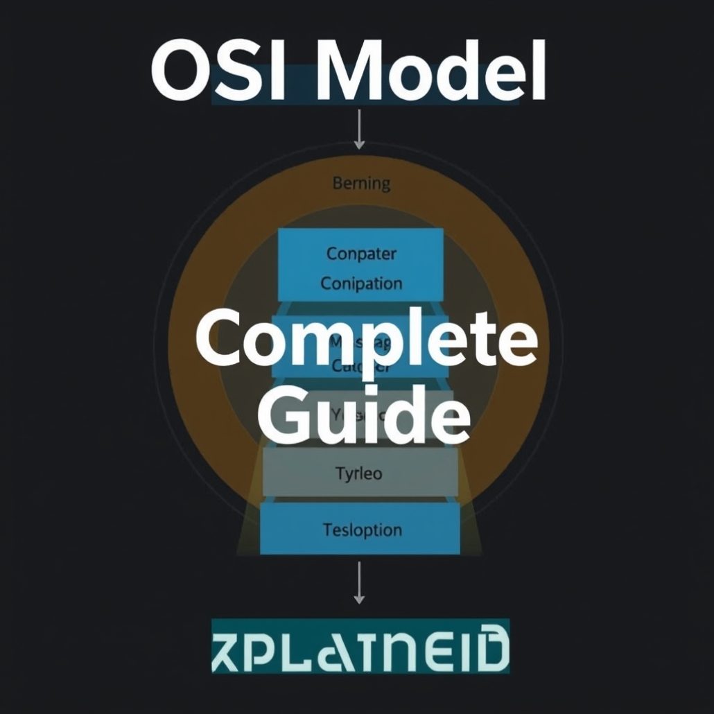
The OSI (Open Systems Interconnection) model is a conceptual framework that standardizes how different network protocols and systems communicate. Developed by the ISO (International Organization for Standardization) in 1984, the OSI model divides network communication into 7 distinct layers, each with a specific function. Every layer communicates with the layer directly above and below it, creating a clean separation of responsibilities that makes network troubleshooting and design much easier.
The OSI model is the foundation of all networking knowledge — it is tested in every major networking certification including CCNA, Network+, and Security+.
| Layer | Name | PDU | Key Protocols/Devices | Function |
|---|---|---|---|---|
| 7 | Application | Data | HTTP, HTTPS, FTP, DNS, SMTP, DHCP | User-facing network services |
| 6 | Presentation | Data | SSL/TLS, JPEG, MPEG, ASCII, Encryption | Data translation, encryption, compression |
| 5 | Session | Data | NetBIOS, RPC, SQL, NFS | Session establishment and management |
| 4 | Transport | Segments | TCP, UDP, port numbers | End-to-end delivery, flow control, error recovery |
| 3 | Network | Packets | IP, OSPF, BGP, EIGRP, Routers | Logical addressing and routing |
| 2 | Data Link | Frames | Ethernet, MAC, ARP, Switches, NICs | Physical addressing, error detection |
| 1 | Physical | Bits | Cables, Hubs, Fiber, Wireless signals | Raw bit transmission over physical media |
Memory tip (top to bottom): “All People Seem To Need Data Processing”
Memory tip (bottom to top): “Please Do Not Throw Sausage Pizza Away”
The Physical layer is the lowest layer and deals with the actual physical transmission of raw bits (1s and 0s) over a physical medium. It defines the electrical, mechanical, and procedural specifications for activating and maintaining physical links between network devices.
The Data Link layer provides node-to-node delivery of data within the same network segment. It packages raw bits from the Physical layer into frames, adds MAC addresses for source and destination, and handles error detection (not correction). It is divided into two sublayers: LLC (Logical Link Control) and MAC (Media Access Control).
The Network layer handles logical addressing and routing — determining the best path for data to travel from source to destination across multiple networks. Unlike Layer 2, which works within a single network segment, Layer 3 works across different networks using IP addresses.
The Transport layer provides end-to-end communication between applications running on different hosts. It is responsible for segmentation, reassembly, flow control, error recovery, and multiplexing using port numbers. The two main Transport layer protocols are TCP (reliable, connection-oriented) and UDP (unreliable, connectionless).
The Session layer establishes, manages, and terminates communication sessions between applications. It handles session checkpointing, recovery, and dialog control (full-duplex vs half-duplex). In practice, many modern protocols combine Session, Presentation, and Application layer functions.
The Presentation layer translates data between the application format and the network format. It handles data encoding, encryption/decryption, and compression so that data sent by one application can be read by another, regardless of the underlying data format differences.
The Application layer is the topmost layer and the one that end users interact with directly. It provides network services to user applications. Note that the Application layer does not refer to the actual application software (like Chrome or Outlook) — it refers to the protocols that applications use to communicate over the network.
| OSI Layer | TCP/IP Layer | Protocols |
|---|---|---|
| Application (7) | Application | HTTP, FTP, DNS, SMTP |
| Presentation (6) | SSL/TLS, encoding | |
| Session (5) | NetBIOS, RPC | |
| Transport (4) | Transport | TCP, UDP |
| Network (3) | Internet | IP, ICMP, ARP |
| Data Link (2) | Network Access | Ethernet, Wi-Fi |
| Physical (1) | Cables, signals |
As data travels down the OSI model from Layer 7 to Layer 1 (sending), each layer adds its own header (and sometimes trailer) — this process is called encapsulation. As data travels up the OSI model at the receiving end, each layer removes its header — this is called de-encapsulation.
| Device | OSI Layer | Reason |
|---|---|---|
| Hub / Repeater | Layer 1 | Simply repeats electrical signals |
| Switch (basic) | Layer 2 | Uses MAC addresses to forward frames |
| Router | Layer 3 | Uses IP addresses to route packets |
| Layer 3 Switch | Layers 2–3 | Switches frames AND routes packets |
| Firewall | Layers 3–7 | Can inspect up to application layer (NGFW) |
| Load Balancer | Layers 4–7 | Works with ports and application data |
| NIC | Layers 1–2 | Physical connection + MAC addressing |
The OSI model provides a systematic approach to network troubleshooting. Start at Layer 1 and work your way up:
The 7-layer structure was designed to separate different networking functions into manageable, independent modules. This allows vendors to develop products for specific layers without worrying about other layers — for example, switch manufacturers focus on Layer 2, while router manufacturers focus on Layer 3.
The OSI model is primarily used as a reference and teaching tool. Real-world networks use the TCP/IP model. However, OSI model terminology (Layer 2, Layer 3, etc.) is universally used by network engineers to describe protocols, devices, and troubleshooting approaches.
Ping uses ICMP (Internet Control Message Protocol) which operates at Layer 3 (Network layer). A successful ping confirms Layer 1, 2, and 3 connectivity between two devices.
Test your OSI knowledge with our free OSI Model Quiz — 20 questions. Also read: TCP Complete Guide | IP Address Guide | Subnet Calculator
Hand-picked articles you might also find useful.
 Networking Fundamentals
 The payload section of the TCP segments contains the actual data being transmitted. Explanation What is the TCP…
 Networking Fundamentals
 What is a Transmission Control Protocol TCP? The Transmission Control Protocol (TCP) is a set of rules that…
 Networking Fundamentals
 The world is quickly running out of IPv4 addresses, and a new version of the internet protocol, IPv6,…